A HIERARCHICAL PRIORITY ENCODER
- Anormal priority encoder encodes only the highest-order data line. But in many situations, not only the highest but the second-highest priority information is also needed.
- The circuit presented here encodes both the highest-priority information as well as the second-highest priority information of an 8-line incoming data.
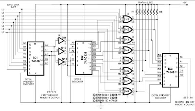
- The circuit uses the standard octal priority encoder 74148 that is an 8-line-to-3-line (4-2-1) binary encoder with active-‘low’ data inputs and outputs.
- The first encoder (IC1) generates the highest-priority value, say, F. The active- ‘low’ output (A0, A1, A2) of IC1 is inverted by gates N9 through N11 and fed to a 3-line-to-8-line decoder (74138) that requires active-‘high’ inputs.
- The decoded outputs are active-‘low’. The decoder identifies the highest-priority data line and that data value is cancelled using XNOR gates (N1 through N8) to retain the second- highest priority value that is generated by the second encoder.
- To understand the logic, let the incoming data lines be denoted as L0 to L7. Lp is the highest-priority line (active-‘low’) and Lq the second-highest priority line (active-‘low’). Thus Lp=0 and Lq=0. All lines above Lp and also between Lp and Lq (denoted as Lj) are at logic 1.
- All lines below Lq logic state are irrelevant, i.e. ‘don’t care’. Here p is the highest-priority value and q the second-highest-priority value. (Obviously, q has to be lower than p, and the minimum possible value for p is taken as ‘1’.) Priority encoder IC1 generates binary output F2, F1, F0, which represents the value of p in active-‘low’ format.
- The complemented F2, F1, and F0 are applied to 3-line-to-8-line (one out of eight outputs is active-‘low’) decoder 74138. Let the output lines of 74138 be denoted as M0 through M7. Now only one line is active-‘low’ among M0 through M7, and that is Mp (where the value of p is explained as above).
- Therefore the logic level of line Mp is ‘0’ and that of all other M lines ‘1’.
- The highest-priority line is cancelled using eight XNOR gates as shown in the figure.
- Let the output lines from XNOR gates be N0 through N7. Consider inputs Lp and Mp of the corresponding XNOR gate. Since Mp = 0 and also Lp = 0, the output of this XNOR gate is Np = complement of Lp = 1.
- All other L’s are not changed because the corresponding M’s are all 1’s. Thus data lines N0 through N7 are same as L0 through L7, except that the highest-priority level in L0 through L7 is cancelled in N0 through N7.
- The highest-priority level in N0 through N7 is the second-highest priority leftover from L0 through L7, i.e. Nq=0 and Nj=1 for q≤7. Now these N lines are applied to priority encoder 2 (IC3) to generate S2, S1, S0, which represent q. Thus the second-highest priority value is extracted.
- Through cascading one can recover the third-highest priority, and so on.
- For example, let L0 through L7 = X X X 0 1 1 0 1.
- Here the highest ‘0’ line is L6 and the next highest is L3 (X denotes ‘don’t care’). Thus p=6 and q=3.
- Now the active-‘low’ output of the first priority encoder will be F2 F1 F0 = 0 0 1. The input to 74138 is 1 1 0 and it outputs M0 through M7 = 1 1 1 1 1 1 0 1. Since M6=0, only L6 is complemented by XNOR gates.
- Thus the outputs of XNORs are N0 through N7 = X X X 0 1 1 1 1. Now N3=0 and the highest priority for ‘N’ is 3. This value is recovered by priority encoder 2 (IC3) as S2 S1 S0 = 1 0 0.

No comments:
Post a Comment